A Fundamental Study on Damage Assessment of the 30-Inch Gas Pipeline
This is an Open-Access article distributed under the terms of the Creative Commons Attribution Non-Commercial License(http://creativecommons.org/licenses/by-nc/3.0) which permits unrestricted non-commercial use, distribution, and reproduction in any medium, provided the original work is properly cited.
Abstract
Oil and gas contribute significantly to achieving the growing demand for energy, which is rising in parallel with population growth. The pipeline system is the main transport system used in the distribution of oil and gas because the pipeline system is considered the most effective and efficient system. The distribution system for gas and oil must guarantee security and safety. Analyzing the pipeline is necessary to ensure distribution security and safety. In this study, a finite element analysis of the gas pipeline specimen was conducted. This analysis is carried out in two stages, first structural analysis and continued with damage analysis, where the damage used is a dent. In the dent analysis, environmental conditions are applied, namely non-pressure, pressure, and full pressure. Then assessed all the results of the analysis of each stage, the assessment was carried out by verifying the results of the analysis with the applicable standard rules. So that the characteristics of the pipeline can be recognized and work accidents caused by operating pipeline failure can be avoided.
Keywords:
Analysis assessment, Dent analysis, Finite element analysis(FEA), Structural analysis키워드:
해석 평가, 덴트 해석, 유한 요소 해석, 구조 해석1. Introduction
Oil and gas projects are at risk due to the large capital investment, the involvement of many parties, the use of complex technology, and high environmental and social impacts. Oil and gas projects need to have a great and secure distribution system due to the risk. A pipeline system is an effective and efficient method for distributing gas and oil, where various distribution routes can be crossed by the pipeline system. Due to the fact that oil refineries are typically located quite far from residential areas or consumer locations, oil and gas distribution is lengthy. This requires that gas pipelines must have a high level of safety. Many accidents that occur in the oil and gas sector are caused by failures that occur in gas pipelines resulting in leaks and explosions. Therefore pipeline integrity is an important thing to consider, pipeline integrity includes the concept of failure prevention, inspection and repair. The pipeline integrity threats can be categorized as follows:
- - Material and construction defect, e.g. defective longitudinal pipe seam, pipe body or joint welds;
- - Mechanical damage from construction, maintenance or third party excavation;
- - Incorrect operation;
- - Corrosion, creep and cracking mechanisms;
- - Device failures and malfunctions;
- - Earth forces such as earthquakes, land slips or telluric currents and weather related threats such as high winds, rough seas or cold/hot temperatures.
(Kishawy and Gabbar, 2010)
Preventive measures are required for asset optimization and security due to the variety of threats. Pipeline reliability starts with the quality of the pipeline being used to keep up with evolving regulatory, economic and applicational demands. As a preventive measure against potential threats to the gas pipeline, a structural analysis was carried out in this study to evaluate the integrity of the pipeline. Following the analysis, the process is continued by analyzing the results of the analysis that was completed and meets the necessary standards. There are several standards such as the American Lifelines Alliance (2005), CEN (the Comité Européen de Normalization) (2006), Canadian Standards Association (2007), and Indian Institute of Technology Kanpur and Gujarat State Disaster Management Authority (2007).
Pipelines are susceptible to a multitude of potential threats that can compromise their integrity and safety. These include corrosion, cracks, mechanical damage, material and manufacturing anomalies, geological hazards, and external interference (Revie, 2015). Based on reports indicating that 50% of operating pipelines contain more than 10 dents after excavation and inspection (Dawson et al., 2002). In addition to analyzing the pipeline under normal conditions, an analysis is also carried out with damage conditions in the form of dent damage. This analysis employs a plain dent analysis, a technique that has been previously utilized in several other studies (Dawson et al, 2018).
Several studies have employed a spherical indenter in their dent analysis. Full-scale test pipes with hemispherical caps, with the objective of investigating the outside cracking of dented pipelines (Arumugam et al., 2018). The full-scale pipe with hemispherical cap is fixed at the bottom by applying an experimental burst test and is then compared with the results of a finite element analysis. (Shuai et al., 2018) also examined a small-diameter API 5L L245 steel pipe without caps with the bottom of the pipe welded with channel steel. This investigation aimed to assess the deformation behavior and strain response of the pipeline during indentation formation, with the results compared to those of a finite element analysis (Shuai et al., 2012). In accordance with the research as mentioned above studies, the present study was performed using a spherical indenter to conduct plain dent analysis.
On dent analysis of pipelines, the area where dents occur can be divided into two parts: the first area being the top of line (TOL) and the bottom of line (BOL). A dent in the upper two-thirds of the pipe’s circumference above the 8 and 4 o’clock is referred to as a top of line dent. And bottom of line dent is defined as being located in the lower third of the pipeline circumference i.e., between the 4 and 8 o’clock orientations. In this study, the type of dent evaluated is top of line dent (Dawson et al., 2018).
Dent analysis was conducted on two categories: constrained and unconstrained. Two different indenter types and two different dent depth variations are used in dent analysis, which is carried out with predetermined boundary conditions. An assessment of pipeline integrity against dent damage is conducted in accordance with several standards, including the American Society of Mechanical Engineers (ASME) B31.8, ASME B31G, American Petroleum Institute (API) 579, API 1160, Canadian Standards Association (CSA) Z662, and UK Onshore Pipeline Association (UKOPA) (Tee and Wordu, 2020; Bernard et al., 2013; Gao and Krishnamurthy, 2015; Dawson et al., 2018).
The study conducted a comprehensive examination of pipeline structural analysis and pipeline damage, specifically dent analysis. The results of each analysis were systematically analyzed. The study is limited to the analysis of constrained and unconstrained plain dents, and does not include other types of damage such as cracks, gouges, welding, or corrosion.
2. Methodology
2.1 Flowchart
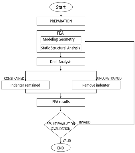
The present study evaluates the pipeline with aim of knowing the characteristic of the pipeline for safety and security. Performed by structural analysis which is then continued with damage analysis, the damage analysis used in this analysis is dent analysis.
As illustrated in Fig. 1, a finite element analysis was conducted using ANSYS Mechanical APDL software, and the analysis results were validated against applicable standards. Following the completion of the structural analysis, the next step is to conduct a damage analysis. A plain dent analysis will be employed, which will be divided into two categories: constraint and unconstraint dent. The results were then verified against applicable standards.
2.2 Pipeline Information
In the present study uses API 5L X70 as a material for the pipeline specimen. Table 1 shows the material properties of API 5L X70.
The principal dimensions shown in Table 2 are used on the gas pipeline specimen in the analysis.
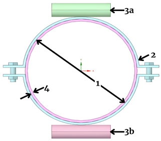
The sectional geometry of the specimen is shown in Fig. 2. ANSYS Mechanical APDL software was used to create a three-dimensional model of the specimen.
The following is an explanation of each part in Fig. 2.
- Part 1: Outer diameter of the pipeline specimen (D)
- Part 2: Jig that adjusts the position of the specimen during the test.
- Part 3: Roller (cylindrical shape), a) which serves as a place to apply the load, and b) serves as a fixed support for the specimen.
- Part 4: Thickness of the pipeline specimen (t)
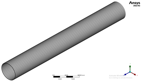
In structural FEA, mesh size is crucial for accurate strain analysis, with smaller meshes on complex geometries and a trade-off between accuracy and computational cost (100mm mesh chosen for this analysis due to moderate complexity), the mesh sizing shows in Fig. 3.
2.3 Non-linear Analysis
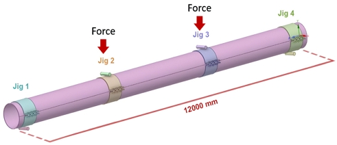
Non-linear analysis is a type of analysis that is widely used in the field of engineering. In addition to the advantages of non-linear analysis in real-world conditions, this analysis also has many advantages compared to linear analysis. Non-linear analysis can be categorized based on several factors, namely material, geometry, and contact. In this study, non-linear analysis is used to obtain more accurate analysis results. For the first analysis, a four-point buckling analysis was conducted. Table 3 presents a series of case variations based on the applied load and different span. The span length, in turn, represents the horizontal distance between two structural support points, or the distance between two jigs to which the load is applied. The boundary conditions for load application, as illustrated in Fig. 4, utilized indenter jigs 2 and 3.
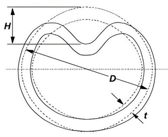
After analyzing the structure, proceed to evaluate the gas pipeline for damage, an example of damage used is a dent, in this study a simple dent is used, where a simple dent is a smooth dent that does not contain wall thickness reductions (such as a gouge or crack) or other defects or imperfections (such as a girth or seam weld). The size of the dent is typically expressed as a percentage of the pipeline's outer diameter (%D). Fig. 5 illustrates the type of dent that can occur in the pipeline.
In Fig. 5, H represents the dent depth of the gas pipeline. In the dent analysis carried out, the top of line dent type was taken. And also applied the two types of depths, 3%D and 6%D. Dent analysis was carried out with two types of indenters of different diameters, a description of the indenter size is shown in Table 4.
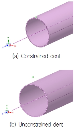
In addition, the damage condition is divided into two categories: constrained dent condition and unconstrained dent condition. A constrained dent is a dent that not free to rebound or re-round, because the indenter is not removed (a rock dent is example of a constrained dent). An unconstrained dent is a dent that is free to rebound elastically (spring back) when the indenter is removed, and free to re-round as the internal pressure changes. Fig. 6(a) and Fig. 6(b) represents the indenter location in both constrained and the unconstrained dent conditions.
In the dent analysis, three categories of conditions are applied, non-pressure, 50% of maximum pressure, and maximum pressure. Based on an ASME safety factor of 0.72, this condition has been made. The formula in equation 1 can be used to determine the pipeline’s maximum pressure.
| (1) |
where σy is yield strength.
The boundary conditions applied to the dent analysis are as shown in Table 5.
The various cases used in the dent analysis are based on the size of the indenter and the depth of the applied dent, as shown in Table 6. In each case, all predefined boundary conditions are applied.
2.4 Standards Assessment
The results of the structural analysis and dent damage analysis of the gas pipeline are validated with the appropriate standard rules. For the validation of the structural analysis of gas pipelines, the strain analysis results are validated with the aforementioned standard rules, including the American Lifelines Alliance (2005), CEN (2006), Canadian Standards Association (2007), and Indian Institute of Technology Kanpur and Gujarat State Disaster Management Authority (2007). The present study employs the strain analysis rule, as issued by the Indian Institute of Technology Kanpur and the Gujarat State Disaster Management Authority, for the structural validation analysis. In accordance with the standard rule, strains are classified into two categories: tensile and compressive. The tensile strain (εt) limits are as follows;
| (2) |
and the theoretical value of local wrinkling of a pipe begins at a compressive strain (εc) as given in the following equation. (ASCE, 1984)
| (3) |
where R is the radius of the pipeline.
In addition to the standard assessment used in pipeline structural analysis, there are also several standard assessments that used as benchmarks for dent analysis, including those shown in Table 7.
3. Result and Discussion
The present research comprises two analyses; a structural analysis and a dent analysis conducted using the finite element method. The following sections present the results of each analysis.
3.1 Structural Analysis
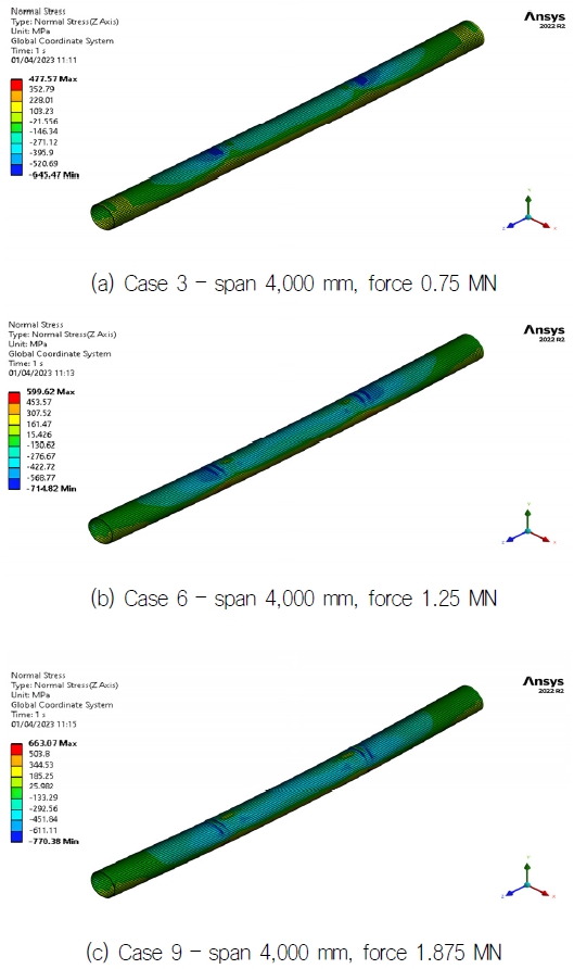
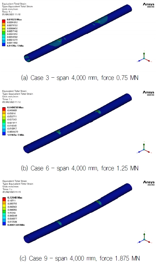
The structural analysis provides several results, including bending stress, deformation, and strain, as illustrated in Figs. 7-9.
In the finite element analysis, the bending stress is represented by the normal stress. Fig. 7 illustrates the effect of varying loads on the stress distribution. As the applied load increases, the stresses also increase. The concentrated load in the jig 2 and 3 areas results in high stresses in these areas.
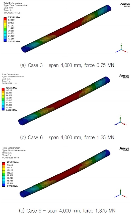
The stress results displayed indicate that the material has exceeded its yield strength limit, which indicates that plastic deformation has occurred. To ascertain the deformation that has occurred, please refer to Fig. 8.
The resulting deformation is linear with respect to the stress that occurs. The area producing high deformation is located within the load application span. The results of the deformation indicate that structural safety cannot be validated. Therefore, further analysis is necessary, specifically the use of the results of strain analysis, which can be validated using applicable standard rules.
Fig. 9 of the strain results indicates that the strain occurs in the area around the jig to which the load is applied. The strain is linear with the stress that occurs to the structure. In this analysis, strain is divided into two types: compressive strain and tensile strain. A summary of the results of the analysis can be found in Table 8.
As previously stated, a strain assessment will be conducted in order to validate the structural safety of the proposed design. This assessment will be carried out in accordance with the established standards. Table 9 presents a summary of the results of the strain analysis validation.
From the assessment results in Table 9, it can be seen that the results of the tensile strain all comply with the standard used as a reference. As for the compressive strain result, only a few cases met, namely cases 1-3.
3.2 Dent Analysis
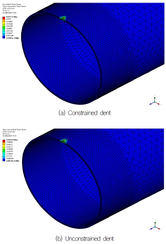
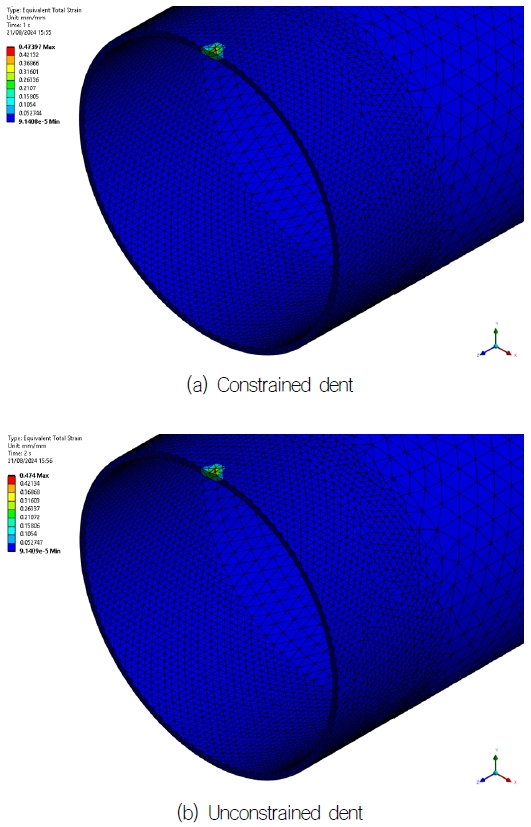
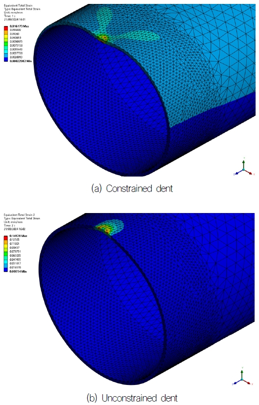
Dent analysis is an advanced analytical technique employed to assess the integrity of a gas pipeline when subjected to damage, particularly in the context of dents. As previously stated in Chapter 2, there are two distinct types of indenter, each with varying pressure conditions. These include non-pressure, 50% of maximum pressure, and maximum pressure. The results of the dent analysis are validated by assessing the strain analysis results against the appropriate standards and guidelines. The results of the strain analysis are presented in Figs. 10-12.
The Figs. 10-12 presents the results of the strain analysis conducted under varying pressure conditions. It can be observed that the internal pressure exerts a significant influence on the analysis of dent, particularly in the case of constrained dent.
As illustrated in Figs. 10-12, the pressure applied to the specimen has a significant impact on the results of the dent analysis, particularly in the case of constrained dent. In this instance, the presence of pressure results in a smaller strain compared to the situation without pressure. This is due to the fact that the pressure provides a resistance force against the applied indenter.
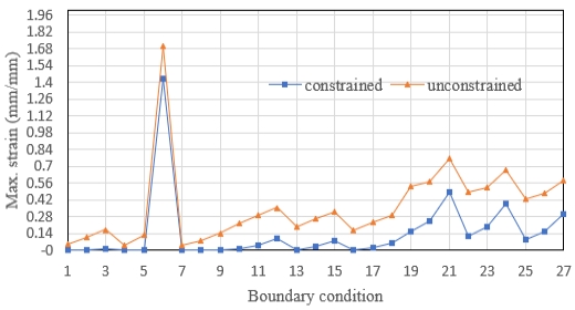
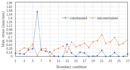
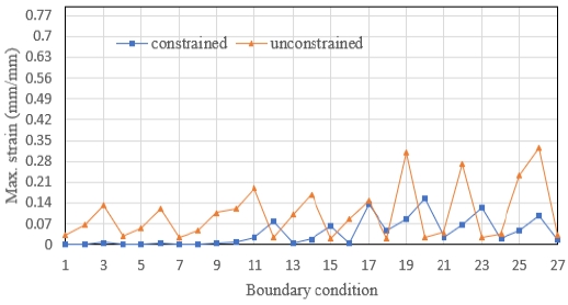
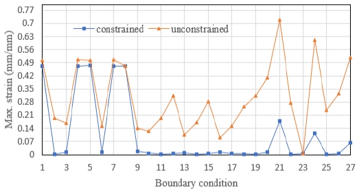
After showing examples of the dent results that occur with three environmental conditions, Figs. 13-16 show the summary results of the dent in each case, where two types of dent analysis were performed, constrained dent and unconstrained dent.
As illustrated in Fig. 13, the graph depicts two types of dent: constrained dent (blue) and unconstrained dent (orange). In accordance with the assessment standards applied, the condition of the pipe is deemed safe if it remains below the maximum strain limit of 6% strain(Table 7), which is equivalent to 0.06. Upon examination of the results of the analysis of case 10, it can be seen that several boundary conditions do not meet the established standards or can be considered unsafe.
The dent analysis for case 11 is summarized and shown in Fig. 14.
The results of the dent analysis in case 11 demonstrate, the unconstrained dent analysis indicates that more boundary conditions exceed the safe limits. The results obtained for cases 10 and 11, in which a small indenter was employed, were less stable when compared to those obtained for cases 12 and 13.
The dent analysis for case 12 is summarized and shown in Fig. 15. that a greater number of boundary conditions satisfy the safe limits in the constrained dent analysis, while the results of unconstrained dent analysis show that there are several boundary conditions that exceed the safety limits.
The dent analysis for case 13 is summarized and shown in Fig. 16.
Case 12 and case 13 are almost the same, the only difference is the depth of the dent applied, where in case 12 the dent depth is 3%D and case 13 is 6%D.
Figs. 13-16 illustrate the results of each case with variations in indenter size and dent depth. From the Figs. 13-16, it can be identified that significant differences exist in each case. Cases with larger indenter sizes demonstrate safer analysis results compared to small indenter sizes, as illustrated in Fig. 15 and 16, which shows relatively small results. This indicates that the indenter area affects the pressure exerted by the indenter on the specimen.
4. Conclusions
In the oil and gas industry, the use of pipelines as a means of distribution is an effective and efficient step. The use of pipelines as the main distributors has many possibilities of damage that can cause many losses in terms of social, economic and environmental aspects, to prevent failure, structural analysis and damage analysis are carried out, an example of damage that is analyzed is dent analysis.
The structural analysis that has been carried out shows that the critical area on the pipeline is in the area around the jig, this is because the area around the jig has excessive interaction when the pipeline is subjected to loads. So that it gives an effect to the pipeline when structural analysis is carried out. In addition to this, determining the length of the span for the jig attached to the pipeline also has an effect on the results of structural analysis, where when the span length is greater it has greater analysis results, this shows that the span length for the pipeline jig takes an important role in the results of the analysis that occurs.
For the damage analysis performed, namely dent analysis, this analysis is carried out with predetermined boundary conditions and also takes into account environmental conditions, The environmental conditions used are non-pressure, 50% of maximum pressure, and maximum pressure. In addition, case variations were applied to the dent analysis based on indenter size and dent depth.
As demonstrated in Chapter 3, the application of pressure to a specimen exerts a resistance force against the dent, influencing the results of the analysis. This phenomenon is particularly beneficial in constrained dents, where the strain produced when pressure is applied is lower than in cases where pressure is not applied.
Furthermore, the findings of this study indicate that when the use of a small indenter results in a greater strain, this is evident from the assessment results for cases involving small indenters. In these instances, several boundary conditions do not meet the safe limit. Conversely, for large indenters, the analysis results on all boundaries are below the safe limit. This indicates that the area of the indenter influences the pressure exerted by the indenter on the pipe. When the indenter with a small area produces a large pressure, a correspondingly large dent is created.
In this study, research on damage to the pipeline is only limited to dent and for future research, it is hoped that research on other pipeline damage will be held and can be used as a reference in gas pipeline installation and operational issues related to pipeline damage.
Acknowledgments
The present study is supported by the “Regional Innovation Strategy (RIS)” through the National Research Foundation of Korea (NRF) funded by Ministry of Education (MOE) (Project Management Number of Foundation: Gwangju Jeonnam Platform 202IRIS-002).
This work was supported by the Korea Institute for the Institute Advancement of Technology(KIAT) grant funded by the Korean Government(MOTIE) (P0017006 ,HRD Program for Industrial Innovation,2024).
References
-
Abdoun, T.H., Ha, D., O’Rourke, M.J., Symans, M.D., O’Rourke, T.D. and Palmer, M.C., et al, 2009. Factors Influencing the Behavior Buried Pipelines Subjected to Earthquake Faulting. Soil Dyn. Earthq. Eng. 29, pp.415-427.
[https://doi.org/10.1016/j.soildyn.2008.04.006]

- American Petroleum Institute (API), “ API Specification 5L, 46th Edition, Line Pipe,”(2018).
- American Society of Mechanical Engineers. Pipeline transportation system for liiquid hydrocarbons and other liquids. ANSI/ASME 2006; B31:4.
- American Society of Mechanical Engineers B31.8, Gas Transmission and Distribution Piping Systems, 2016.
- American Society of Mechanical Engineers B31.8S, Managing System Integrity of Gas Pipeline, ASME Code for Pressure Piping, B31 Supplement to ASME B31.8,2016.
- American Society of Mechanical Engineers B41.4, Pipeline Transportation System for Liquids and Slurries, 2016.
-
Arumugam, U., Gao, M., Krishnamurthy, R., Wang, R., Kania, R., 2018. Study of safe dig pressure level for rock dents in gas pipelines. Int. Pipeline Conference ASME, Calgary, AB, Canada.
[https://doi.org/10.1115/IPC2018-78616]

- Bannantine, Julie A., Comer, Jess J. and Hardrock, James L., 1989. Fundamental of metal fatigue analysis. New Jersey: Prectice Hall.
-
Bernard, M., Fontanabona, J., Gaffard, V., Popineau, D. and Wiet, P., 2013. New horizons for pipelines integrity assessment. Offshore Technology Conference, Houston, TZ, USA.
[https://doi.org/10.4043/24015-MS]

- Bood, R.J., Galli, M.R., Marewski, u., Roovers, P., Steiner, M. and Zaréa, M., 1999, EPRG Methods for assessing the tolerance and resistance of pipelines to external damage part 1+2, European Pipeline Research Group, pp.806-811.
- Cosham, A. and Hopkins, P., 2003. The effect of dents in pipelines-guidance in the pipeline defect assessment manual, International COnference on Pressure Vessel Technology (ICPVT-10), Vienna.
- Dawson, J., Murray, I. and Hedger, J., 2018. Techniques for the enhanced assessment of pipeline dents. J. Pipeline Eng. 17, pp.127-135.
- Dawson, S.J., Russell, A. and Patterson, A., 2002. Emerging techniques for enhanced assessment and analysis of dent. Proc. Int. Pipeline Conf., Calgary, AB, Canada.
-
Gantes, C.J. and Melissianos, V.E., 2016. Evaluations of seismic protection methods for buried fuel pipelines subjected to fault rupture front. Buried Pipeline Protection against Faulting,Volume 2, pp.1-12.
[https://doi.org/10.3389/fbuil.2016.00034]

-
Gao, M. and Krishnamurthy, R., 2015. Mechanical damage in pipelines: a review of the methods and improvements in characterization, evaluation, and mitigation. Oil Gas Pipelines, pp.289-326.
[https://doi.org/10.1002/9781119019213.ch22]

- Indian Institute of Technology Kanpur and Gujarat State Disaster Management Authority, “IITK-GSDMA Guidelines for Seismic Design of Buried Pipelines”(2007).
- Jang, Y.C., Kim, I.J., Kim, C.M., Baek, J.H., Kim, Y.P., Kim,. W.S., Jeon, B.G. and Chang, S.J., 2019. A study on the load carrying capacities of natural gas pipeline using in-plane bending experiment and finite element analysis. 2019 Annual Meeting of Korean Society of Mechanical Engineers, pp.941-943.
- Kennedy, John L., 1993. Oil and gas pipeline fundamentals. TUlsan: PennWell Publishing Company.
-
Kishawy, H.A. and Gabbar, H.A, 2010. Review of pipeline integrity management practices. International Journal of Pressure Vessels and Piping, 87, pp.373-380.
[https://doi.org/10.1016/j.ijpvp.2010.04.003]

- PDAM, ‘The Pipeline Defect Assessment Manual (PDAM), A report to the PDAM Joint Industry Project, Edition 2, October 2016.
- Revie, R.W., 2015. Oil and gas pipeline: integrity and safety handbook. John Wiley & Sons, New York, USA.
-
Rodhi, N.N., Anwar, N. and Wiguna, I.P.A., 2017. A review on risk factors in the project of oil and gas industry. IPTEK, The Journal for Technology and Science, 28(3), December 2017.
[https://doi.org/10.12962/j20882033.v28i3.3217]

- Sears, F.W., 1944. Mechanics, Heat and Sound. Cambridge, Massachusetts: Addison-Wesley.
-
Shuai, Y., Shuai, J. and Zhang, X., 2018. Experimental and numerical investigation of the strain response of a dented API 5L X52 pipeline subjected to continuously increasing internal pressure. J. Nat. Gas Sci. Eng. 56, pp.81-92.
[https://doi.org/10.1016/j.jngse.2018.05.037]

-
Shuai, Y., Wang, X., Shuai, J., Zhao, Y. and Tang, C., 2020. Mechanical behavior investigation on the formation of the plain dent of an API 5L L245 pipeline subjected to concentrated lateral load. Eng. Fail. Anal. 108, 104189.
[https://doi.org/10.1016/j.engfailanal.2019.104189]

-
Soehaimi, A., Baskoro, S. R. S., Seobowo, E., Ma’mur and Sopyan, Y., 2021. Assessment of potential earthquake and tsunami disaster for protection oil and gas infrastructure and PLTU in Cilacap central java. Journal of Geology and Mineral Resources, 22(4), pp.209-221.
[https://doi.org/10.33332/jgsm.geologi.v22i4.657]

-
Tee, K.F. and Wordu, H.H., 2020. Burst strength analysis of pressurized steel pipelines with corrosion and gouge defects. Eng. Fail. Anal. 108, 104347.
[https://doi.org/10.1016/j.engfailanal.2019.104347]

- UKOPA, UK onshore pipeline operators’ association – Industry good practice guide, managing pipeline dents, UKOPA/GP/004, Edition 1, 2016, Derbyshire, UK.
-
Wu, Y. et all, 2023. A new evaluation methods of dented natural gas pipeline based on ductile damage, Applied Ocean Research, 135, pp.1-12.
[https://doi.org/10.1016/j.apor.2023.103533]


