유조선 좌초 사고 시 2차사고 방지를 위한 잔류강도 평가기술 개발
Abstract
The aim of this study is to develop a rapid calculation technique of the residual strength in order to prevent sequential events under grounding accidents. Very Large Crude-Oil Carrier (VLCC), Suezmax, and Aframax double hull oil tankers carrying large quantities of crude oil were selected for target structures. The rock geometries are chosen from the published regulation by Marine Pollution Treaty (MARPOL) of the International Maritime Organization (IMO). Oceanic rocks as the most frequently encountered obstruction with ships are applied in this work. Damage condition was predicted using ALPS/HULL program based on grounding scenario with selected parameters, i.e. depth of penetration, damage location and tanker type. The results of the scenarios are quantified to form an empirical formula which can evaluate the residual strength. The proposed formula is validated by applying a series of random grounding scenarios.
Keywords:
Ship-ship grounding, Oil tankers, Residual strength, Shape function of rock, Estimation equation키워드:
선박 좌초, 유조선, 잔류강도, 암초 형상 함수, 추정 식1. 서론
선박은 연근해 운항 또는 계류 중 좌초와 충돌 같은 예기치 못한 사고가 발생하며, 대형 유조선은 타 선종에 비하여 막대한 양의 원유 유출로 인한 심각한 인명, 재산 및 환경피해를 초래한다.
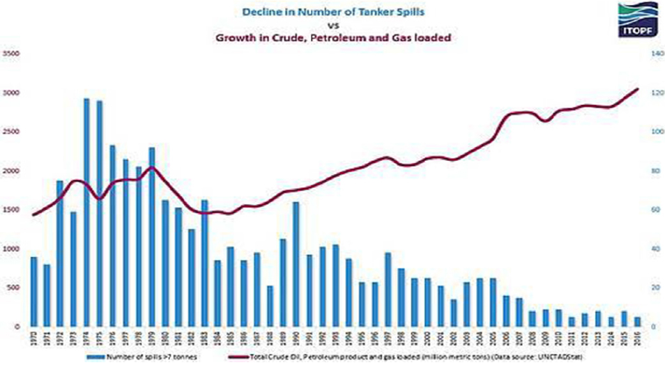
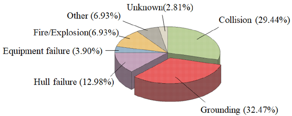
International Tanker Owner Pollution Federation (ITOPF)의 통계 (ITOPF, 2017)에 따르면 (Fig. 1) 유조선 사고로 인한 원유 유출 사건은 점차 감소하는 반면, 선박의 대형화로 인하여 원유 적재량은 꾸준히 증가하는 것을 알 수 있다. 또한 충돌과 좌초 같은 해양사고로 인한 원유 유출량이 전체 사고의 60% 이상으로 가장 큰 것으로 조사된다 (Fig. 2).
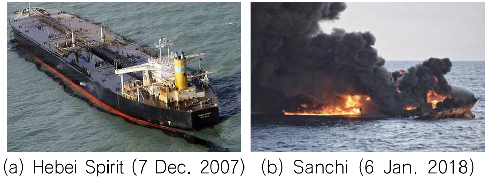
이는 유조선 사고 시 위험성을 암시하고 있으며, 이에 따른 환경, 인명 및 재정적 피해 등과 같은 2차 사고를 줄이기 위하여, 사고 즉시 선박의 손상거동을 파악하는 것이 중요하다. 특히 태안반도 사건으로 알려진 2007년 12월 7일 Hebei Spirit 사건과 (Fig. 3 (a)) 한반도 근처 동중국해에서 2018년 1월 6일 발생한 Sanchi 유조선 침몰 사건을 (Fig. 3 (b)) 통하여 국내에서도 유조선 사고로 인한 피해의 심각성을 각인 시킨바 있다.
이러한 배경으로 인하여 International Maritime Organization (IMO)의 Marine Pollution Treaty (MARPOL) 에서는 선박의 좌초사고 통계를 바탕으로 암초 형상을 확률론적 무차원화 된 변수로 제시하고 있다 (IMO, 2003). 또한 국제선급협회 (International Association of Classification Societies, IACS) 에서는 기존의 유조선과 산적화물선의 공통구조규칙을 조화 공통구조규칙 (H-CSR) (2017)으로 통합시키면서 선박의 잔류 강도를 보수적으로 평가하는 등 사고 후 잔류 강도에 대한 중요성이 대두되고 있다.
한편, Lee et al. (2016)은 유체구조연성 효과를 고려한 충돌 및 좌초 사고 시 전선 침몰 시뮬레이션 기법을 개발하였다. 또한, Cho et al. (2018)는 비 보강 강판을 대상으로 구조물 충돌에 관하여 크기 효과 (scale effect)가 소성변형에 미치는 영향을 정량적으로 규명하였다. Prabowo et al. (2017) 은 선박 충돌 및 좌초 사고 시뮬레이션을 통하여 피 충돌선의 선체 표면의 찢어짐 현상 (tearing)과 내부 에너지를 고찰하였으며, Paik et al. (2012)은 선박의 좌초 사고 시 손상지표를 수식화하여 선박의 구조적 안전성을 추정하였다. 본 연구의 선행 연구 (Baek et al., 2018)는 정량적 기법을 통하여 대형 유조선의 선박-선박 충돌 사고 시 잔류 강도 추정식을 개발하는 등 선박의 구조 안전성을 확보하기 위한 연구가 활발하게 진행되고 있다.
본 연구에서는 대형 유조선을 대상으로 좌초(grounding) 사고 시 2차 피해를 줄이고 초기 사고 대책을 세우기 위하여, 잔류강도를 빠르게 계산할 수 있는 기법 개발에 목적을 두고 있다. 이를 위하여 IMO가 제시한 확률론적 암초 형상을 선정하였다. 암초의 침투에 따른 선각의 잔류강도에 미치는 영향을 정량적으로 평가하기 위하여 사고 시나리오를 선종에 따라 정의하였으며, 시나리오 별 잔류 강도 값의 경향을 바탕으로 경험식을 개발하였다.
2. 대상 구조물
2.1 암초 형상
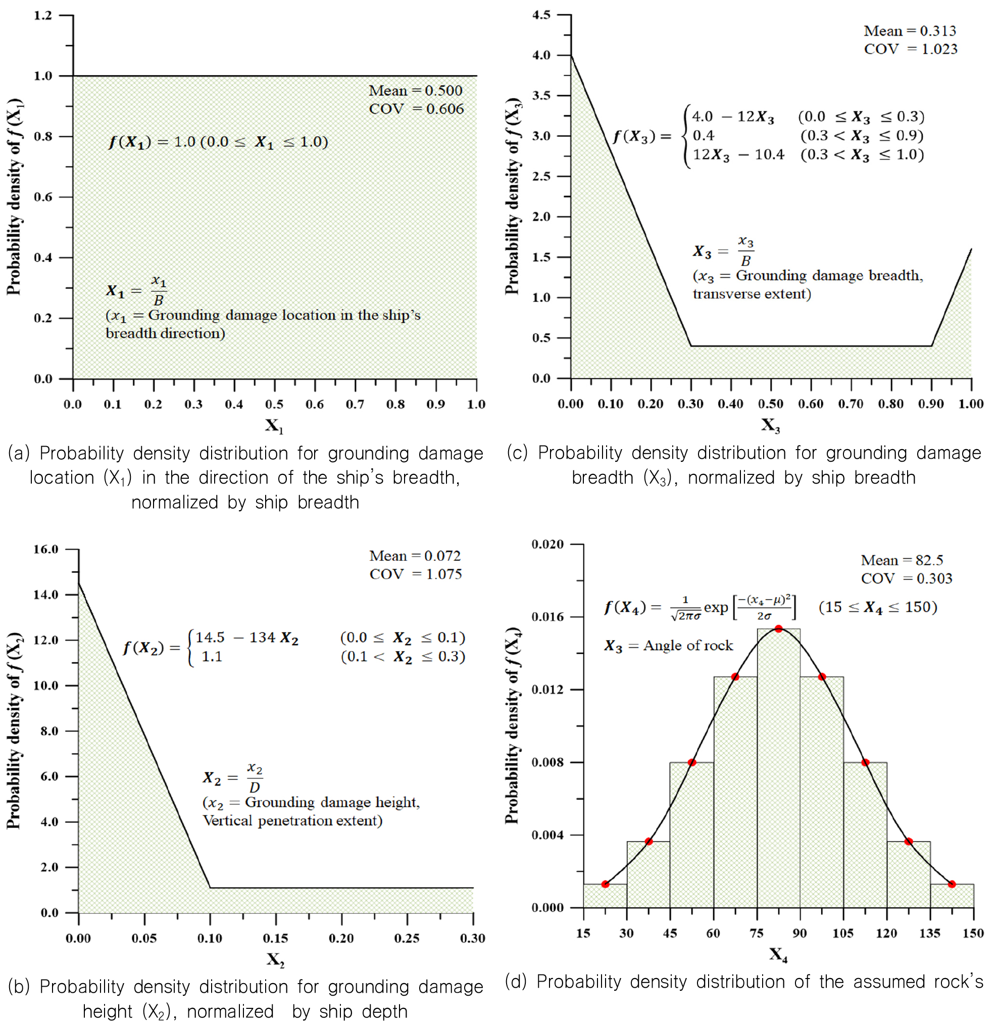
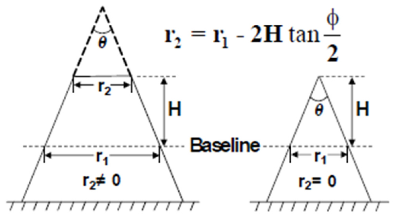
암초의 형상은 MARPOL에서 제시한 암초의 크기 변수를 확률론적으로 무차원화 한 그래프를 이용하였으며 Fig. 4 (a)-(c) 암초 상단부의 각도는 정규분포를 가정하였다 (Fig. 4 (d)).
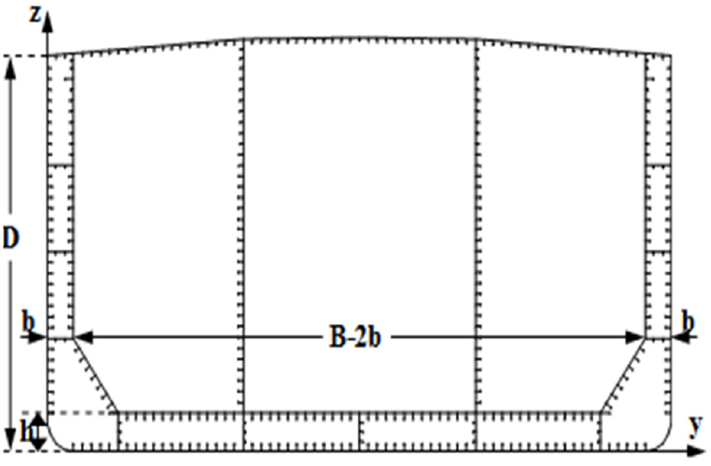
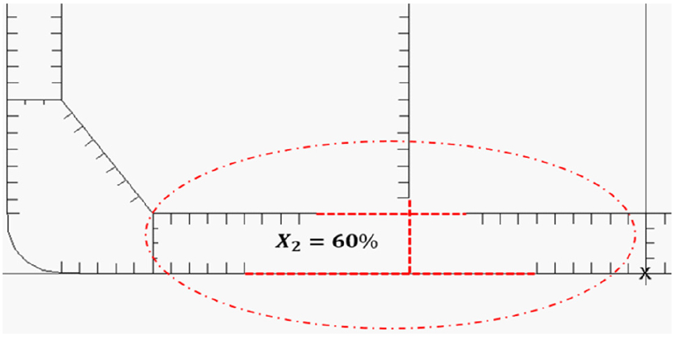
보수적인 평가를 위하여 확률이 가장 높은 구간을 포함하는 가장 큰 값을 채택하였다 Table 1. X1은 선각의 폭 방향 좌초 위치 변수이며, X2는 암초의 좌초 침투 깊이이다. X3은 종속 변수로서 Fig. 5의 식에 기초하여 암초의 크기를 결정할 때 사용 하였으며, X4는 정규분포의 구간 중 확률이 가장 큰 구간의 가장 큰 값인 90도로 고정하여 보수적 평가를 진행하였다. 좌초 시 좌초의 침투 깊이는 내부 선저에 심각한 영향을 줄 수 있으므로, 선체 높이의 20% 까지의 침투깊이를 고려하였다. 따라서 결정된 암초의 제원은 피 충돌선의 크기에 따라 달라지며 Table 2와 같다.
3. 좌초 시나리오
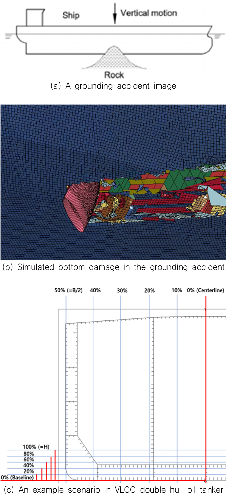
본 연구에서는 선각 중앙부 손상을 가정함으로서 보수적으로 좌초 손상을 가정하였으며, 손상 형태는 Fig. 7(a)-(b)와 같이 암초의 상단 형태와 유사한 특징이 있다. 또한 암초의 최종 침투 위치로 피 충돌선의 손상크기 및 잔류강도를 예측할 수 있으며 암초 침투 깊이가 깊을수록 손상되는 폭이 점진적으로 증가한다. 본 연구의 시나리오 주요 변수는 X1과 X2로서 폭 방향 좌초 위치 (X1) 및 암초의 침투 깊이 (X2)에 따라 시나리오를 설정하였다.
시나리오 선정은 선종별로 분류하였으며, X1 (폭 방향 좌초 위치)은 전 구간 동일 확률로 좌우 대칭을 이용하여 중앙선 (X1= 0%)에서 선측 (X1= 50%)까지 반폭에 대하여 등분하였다. X2 (암초 침투깊이) 또한 암초의 전체 높이 (H)를 기준으로 등분하여 정의하였다.
4. 좌초 사고 유조선의 잔류 종강도 계산
4.1 해석 프로그램
시나리오 모델에 대한 강도 해석은 Paik et al. (2012)에 의해 정확성이 검증된 Intelligent Supersize Finite Element Method (ISFEM)을 사용하는 ALPS/HULL 해석 프로그램을 사용하였다.
본 프로그램은 Fig. 8과 같이 판-보강재가 분리된 구조를 적용하여 계산속도가 빠르며 (Paik and Thayamballi, 2003), (ALPS/HULL,2012), 해석의 정확성은 실험 및 기타 연구들을 통하여 검증된 바 있다 (ISSC, 2012), (Paik et al., 2013).
4.2 초기 결함
선박은 건조 단계에서 열로 인한 처짐 및 잔류응력과 같은 초기결함이 발생하게 된다. IACS (2009)의 8장 ‘capacity assessment’ 에 따르면 구조 강도 해석 시, 용접에 의한 초기 처짐을 반드시 고려하게 되어있다. 본 연구에서는 Fig. 9와 같이 International Standards Organization (ISO) (2007)에서 제공하는 판의 좌굴 모드와 보강재 형상의 처짐이 고려되었다. 초기 처짐은 다음 식 (1)과 식 (2)를 이용하여 정의 된다.
| (1) |
여기서, Wopl, Woc,Wos= 판 및 보강재의 최대 초기 처짐, 그리고 A0, B0, C0=최대 처짐 값으로 식 (2)와 같이 정의 된다 (Paik and Thayamballi, 2003).
| (2) |
여기서, β=판의 세장비, tp=판의 두께, 그리고 a=판의 길이이다.
4.3 손상 후 선각 모델링
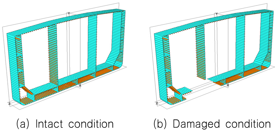
IACS (2014)에 따르면 손상된 구조물의 모델링은 선체의 폭과 깊이 방향에 대하여 손상위치와 범위로 이상화하고 길이방향 손상정도는 고려하지 않는다. 따라서 손상된 요소는 선체 거더 강도에 기여하지 않기에 Fig. 10과 같이 선각의 잔류 종강도 평가 시 모델에서 제거하는 ‘damaged element removal method’를 사용하였다 (IACS, 2014).
4.4 좌초 사고 시 잔류 종강도 해석 결과
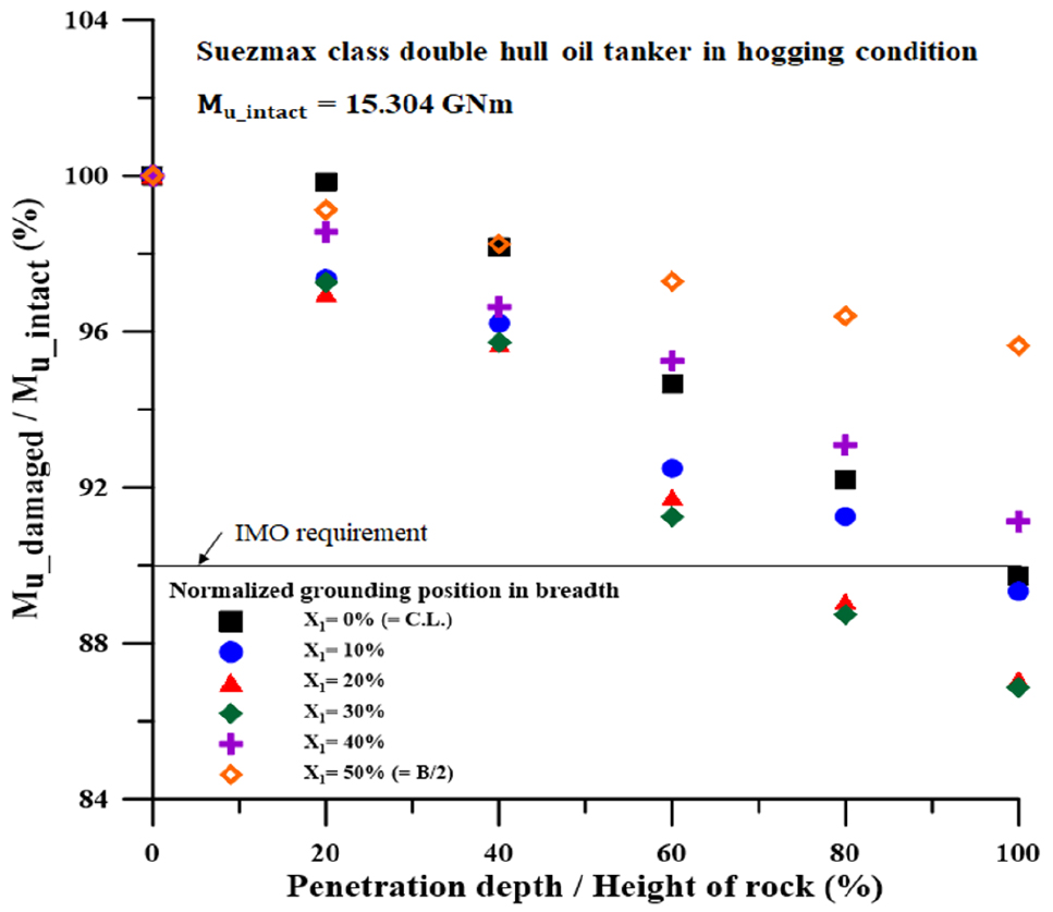
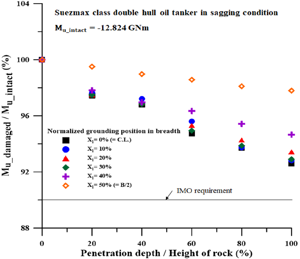
좌초 시나리오에 따른 선저 손상의 증가에 따라 전체적으로 강도가 감소하는 종강도 곡선을 보인다. 또한 손상을 받지 않은 단일 갑판에 압축을 가하는 새깅의 경우 호깅 시보다 전체적으로 낮은 종강도를 보인다. 한편 IMO (2000)는 온전한 상태에서의 강도 기준으로 손상 후 90% 이상의 잔류 강도를 요구하고 있다.
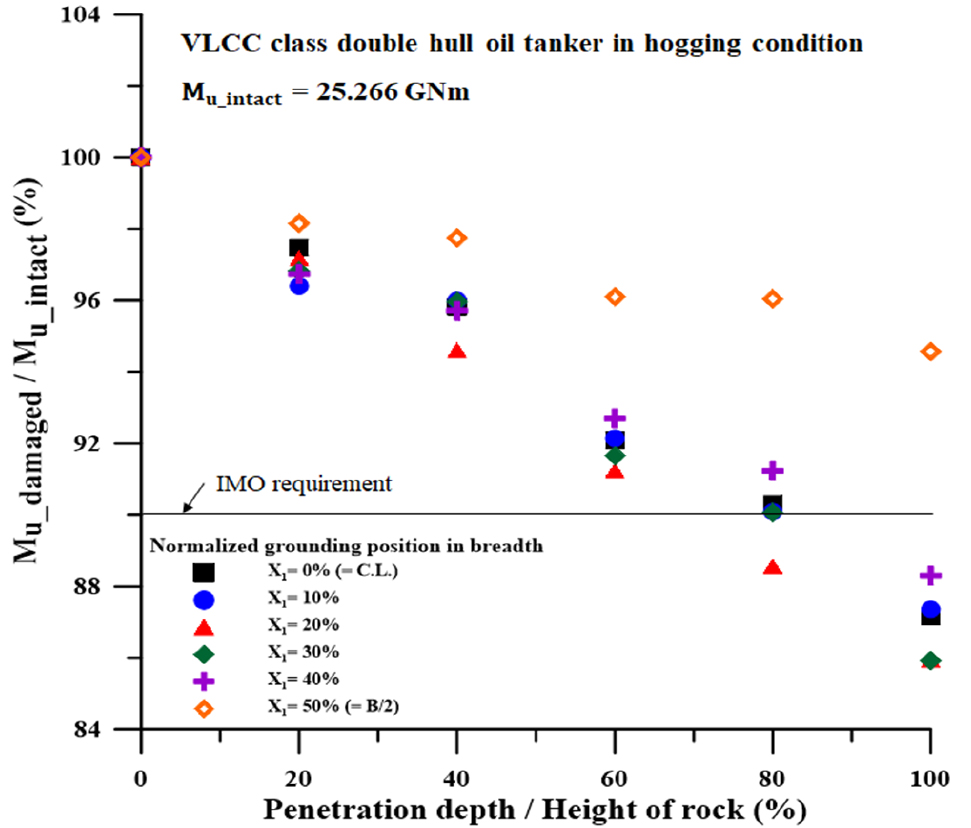
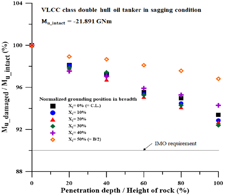
VLCC 이중선체 유조선을 대상으로 폭 방향 침투 위치(X1) 및 깊이(X2)에 따른 손상 시나리오 별 해석을 수행하였으며, 잔류 최종 종강도의 결과 값은 Fig. 11 및 Fig. 13과 같다. 암초의 점진적 침투는 선저부에 손상면적이 증가하고 2차 면적모멘트 및 종강도의 감소로 이어진다.
호깅 상태 시 (Fig. 11), 암초의 침투 깊이가 (X2) 80% 일 때부터 IMO 기준을 만족하지 못하기 시작하였으며, 특히 X2= 100%일 때는 폭 방향 좌초위치가 (X1) 100%인 시나리오를 제외하면 전체가 IMO 기준을 만족하지 못하였다. 기준을 만족한 시나리오인 X1= 100%는 암초의 절반이 선각에 손상을 입히지 못한 것이 주요인으로 사료된다.
한편 Fig. 12와 같이 암초의 침투 깊이 (X2)가 60%에서부터 이중선저의 내판에 손상이 가해지기 시작하였으며 전체 시나리오 공통적으로 강도 감소율이 급증한 것을 확인할 수 있다. 이로 인하여 호깅시 침투 깊이 80%에서부터 IMO강도 규정을 초과한 강도 손실이 발생한 것으로 사료된다.
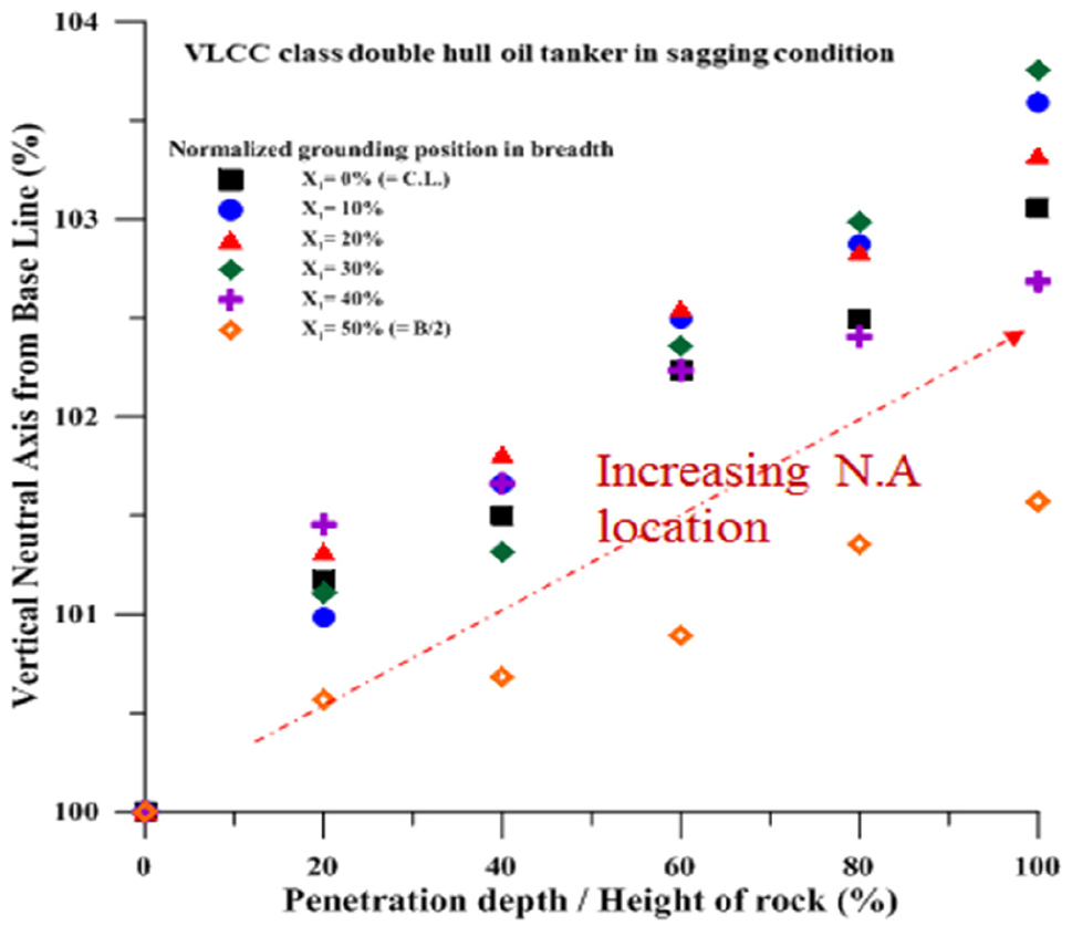
새깅 시 (Fig. 13), 전체 시나리오가 IMO 기준을 만족하였다. 새깅 강도에 지배적인 갑판의 손상이 없음으로 인한 적은 강도 손실을 보였다. 또한 이중 선저부 손상에 따른 중립축의 높이가 상승하였으며 Fig. 14, 이로 인하여 단일 갑판의 압축에 대한 모멘트 길이가 짧아짐에 따라 종강도 감소량이 줄어든 것으로 사료된다.
VLCC와 유사하게 Suezmax를 대상으로 좌초 사고 시 잔류 강도해석을 수행하였으며, 결과는 Figs. 15, 16과 같다.
호깅 시 (Fig. 15), 폭 방향 좌초위치가 (X1) 40%인 경우 암초의 하단부가 선각의 손상에 영향을 주지 못하여 IMO 기준을 전체적으로 만족하였다. 반면 X1= 0%, 10%, 20%, 30%의 시나리오의 경우 각각 센터 거더 또는 사이드 거더와 같은 주요 부재에 손상을 가하며 기준을 초과한 종강도 감소율을 나타내었다.
새깅 시 Fig. 16, 암초의 침투 깊이가 (X2) 60% 일 때 선저 내판의 손상이 시작됨으로 인한 전체적으로 급격한 잔류 종강도의 감소가 관찰되었다. 한편, VLCC의 새깅 상태 결과와 같은 이유로 전체 시나리오가 IMO 기준을 만족하였다.
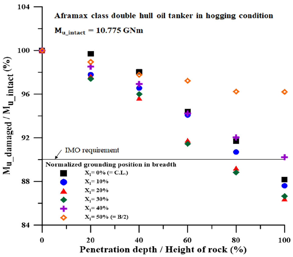
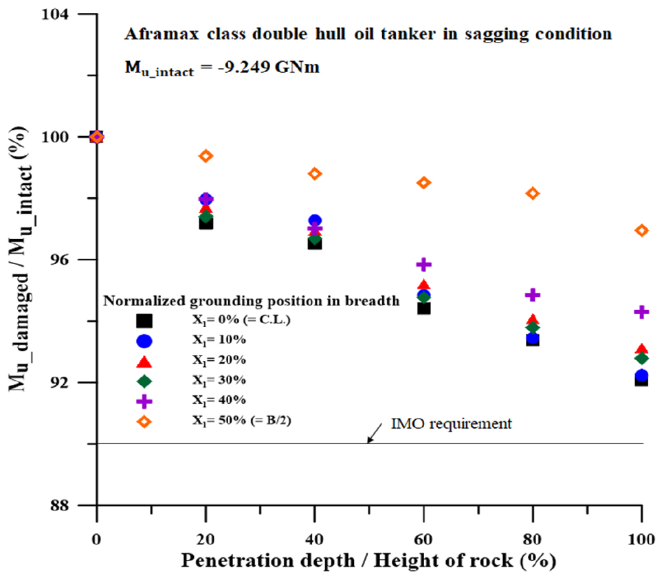
VLCC, Suezmax와 유사하게 시나리오에 따른 Aframax 급 이중선체 유조선의 잔류 종강도 해석 결과는 Figs. 17, 18과 같다.
호깅 시 (Fig. 17), 폭 방향 좌초위치가 (X1) 30%, 암초의 침투 깊이가 (X2) 60%에서 4.5% 감소로 가장 큰 폭의 잔류 종강도 손실을 보였는데, 사이드 거더 및 선저내판 에 동시에 큰 손실을 가한 것이 주요인이다.
새깅 시 (Fig. 18)에서도 유사하게 X2= 60% 이후 잔류 강도가 큰 폭으로 감소하였지만 VLCC, Suezmax의 경우와 동일하게 IMO의 잔류종강도 기준을 모두 만족하였다.
5. 잔류 종강도를 이용한 경험식 개발
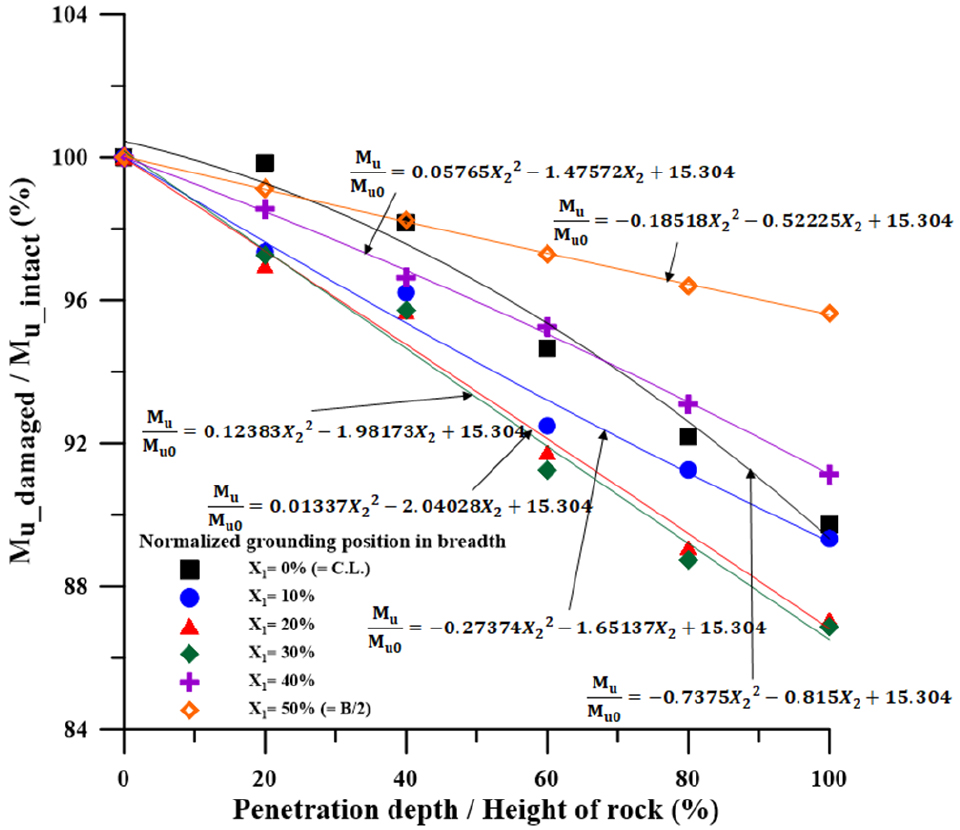
암초로 인한 좌초 손상 시나리오별 해석결과는 폭 방향 손상위치(X1), 암초 침투 깊이(X2) 및 이중선체 유조선의 급에 따라 각각 다르게 잔류 종강도에 영향을 미치고 있다. 본 장에서는 이러한 특성을 반영하기 위하여 결과 그래프의 경향을 변수 ‘X1’과 ‘X2’를 이용한 함수를 식 (3a), (3b)과 같이 추정한다.
| (3a) |
| (3b) |
Fig. 19와 같이 좌초 시나리오에 따른 암초 침투 깊이별 잔류 종강도의 추정식을 만든 후, 각 계수들을 폭 방향 위치 변수 X1에 대해 추정하여 식 (3a), (3b)의 미지계수 a, b, c를 결정한다.
한편 IACS의 조화 공통구조규칙 (H-CSR) (2017)에 따라 유조선의 이중선체와 같은 주요 구조물의 위치와 최소 간격이 규정되어 있다 (chap. 2.3 height of double bottom, and chap. 3.2.2 minimum clearance dimensions). 따라서 무차원화 된 변수 X1과 X2를 사용하여 개발한 추정식은 같은 급의 타 선종에서도 유의미하다. 또한 본 장에서 개발된 식의 좌항인 강도 값은 무차원화 된 값으로 Mu0에 식을 적용할 선박의 사고 전 상태의 종강도를 대입 후, 사고 시의 X1과 X2를 입력함으로서 해당 선박의 잔류 강도를 추정할 수 있다.
5.1 VLCC 급 이중선체 유조선
식 (3a), (3b)에 대한 VLCC 급 이중선체 유조선의 잔류 종강도 경험식의 미지계수는 Table 4와 같다.
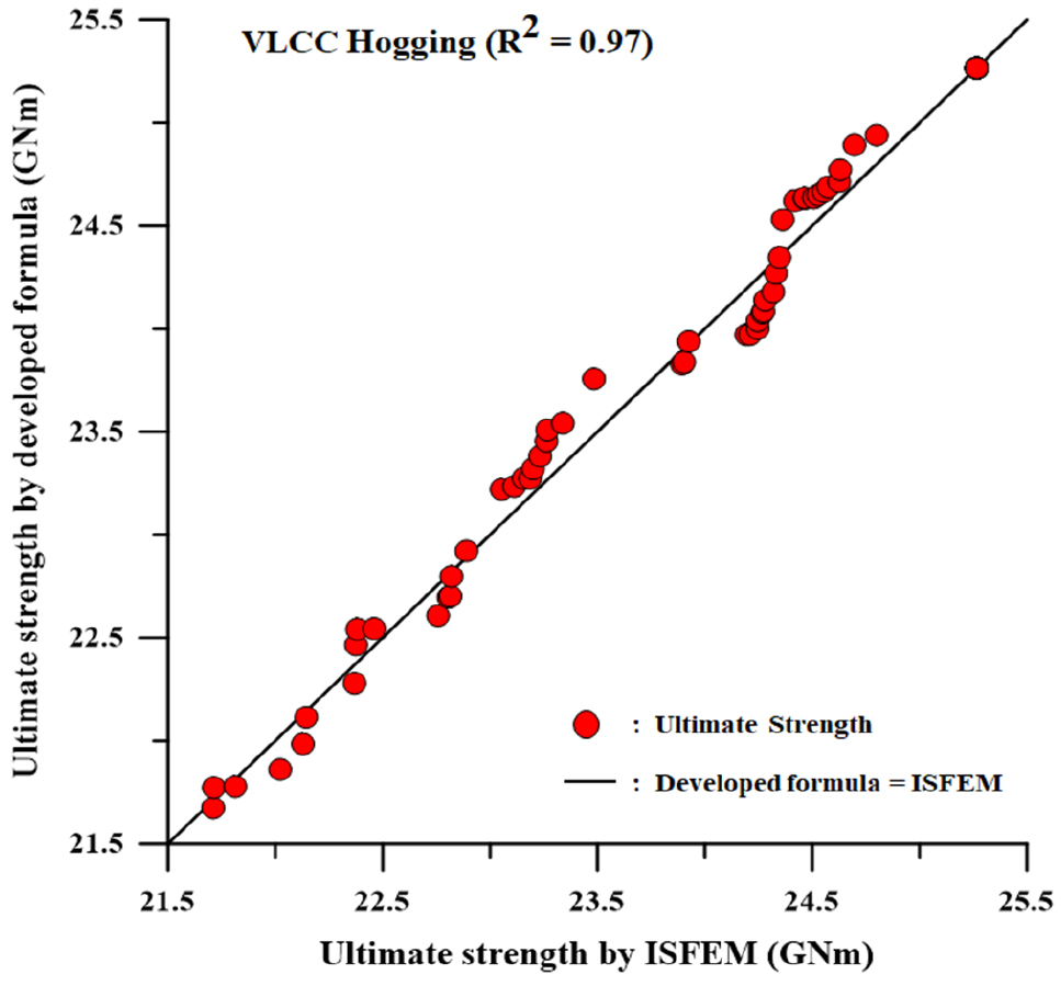
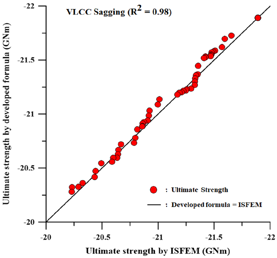
개발된 경험식의 정확성 검증을 위하여 Table 4에 정의된 미지계수를 식 (3a), (3b)에 적용하고 기존의 손상 시나리오와 중복되지 않는 임의 시나리오를 가정하여 해석을 수행한다. 임의 시나리오에는 X1= 5%, 15%, 50%, 95%를 사용하였으며, 전체 암초 침투 (X2)를 가정하여 진행하였다. 결과는 Fig. 20, Fig. 21과 같이 개발된 경험식과 프로그램 해석 결과를 비교하였으며, 일치 경향을 나타내는 R2 값을 이용하여 도식화하였다.
5.2 Suezmax 급 이중선체 유조선
식 (3a), (3b)에 대한 Suezmax 급 이중선체 유조선의 잔류 종강도 경험식의 미지계수는 Table 5와 같다.
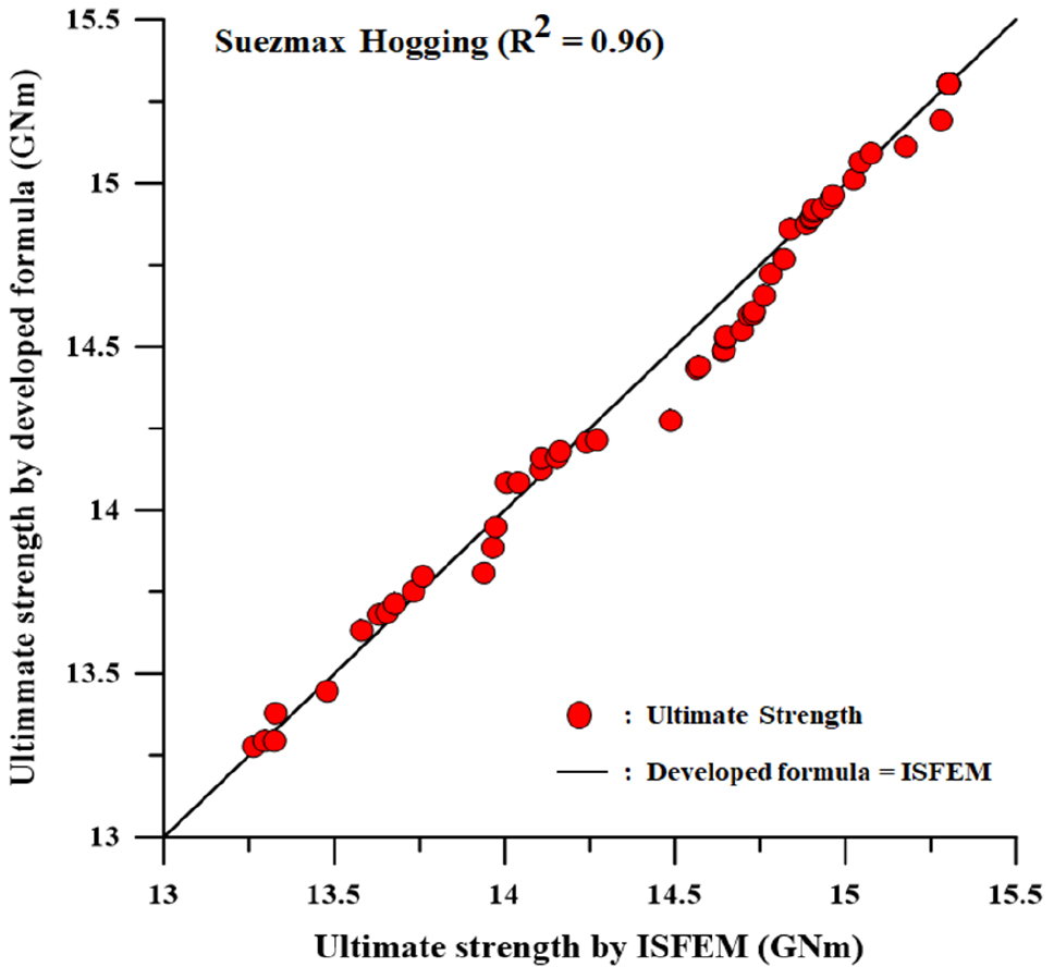
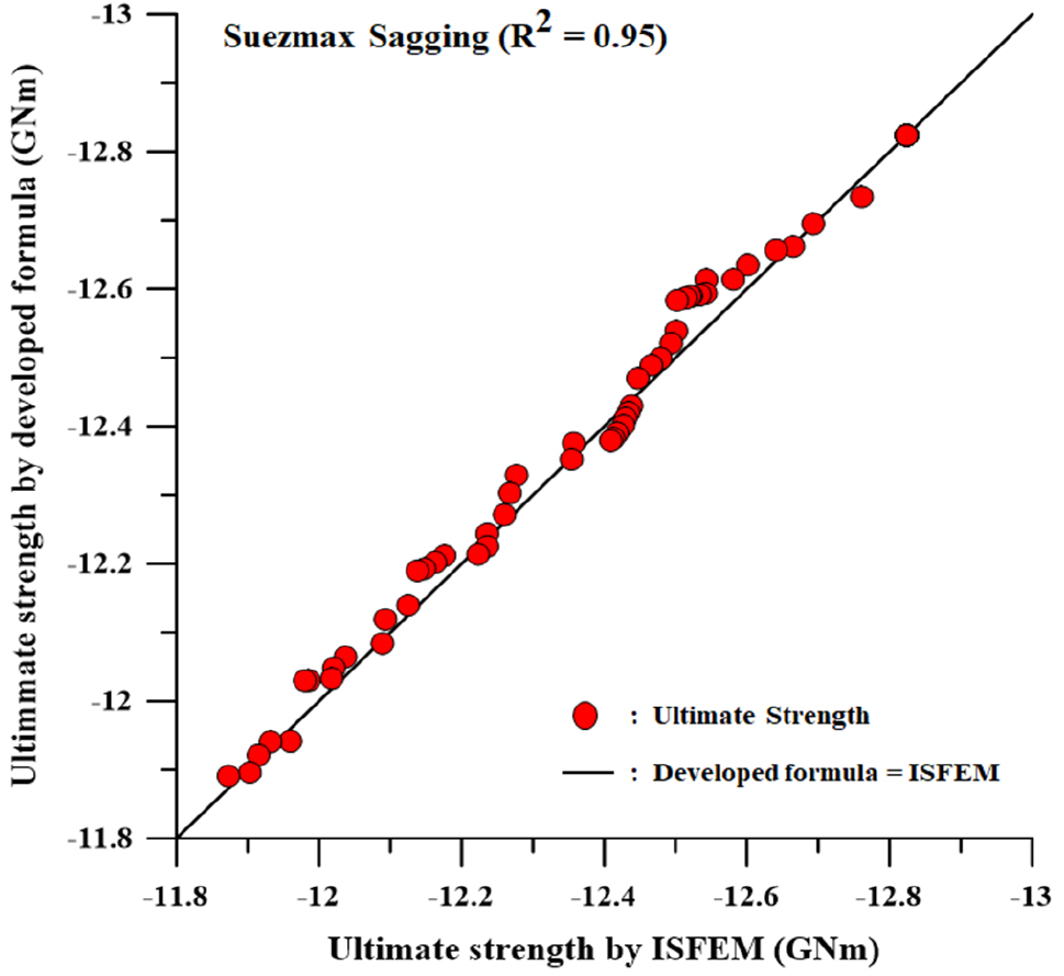
5.1.2절과 같은 방식으로 경험식 검증에 임의 시나리오 X1= 15%, 45%, 70%, 90%를 적용하였다. Figs. 22, 23과 같이 경험식의 해석 결과와 ISFEM 프로그램 해석 결과를 비교 및 R2을 이용하여 일치성을 나타내었다.
5.3 Aframax 급 이중선체 유조선
식 (3a), (3b)에 대한 Aframax 급 이중선체 유조선의 잔류 종강도 경험식의 미지계수는 Table 6과 같다.
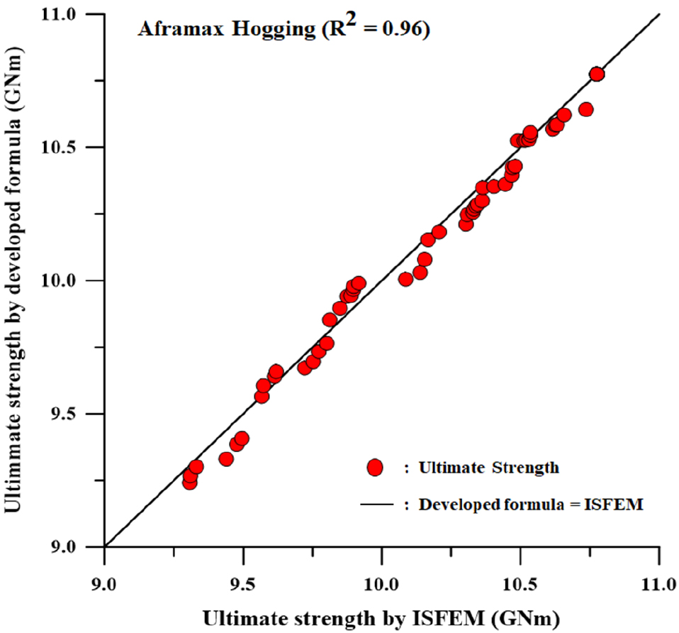
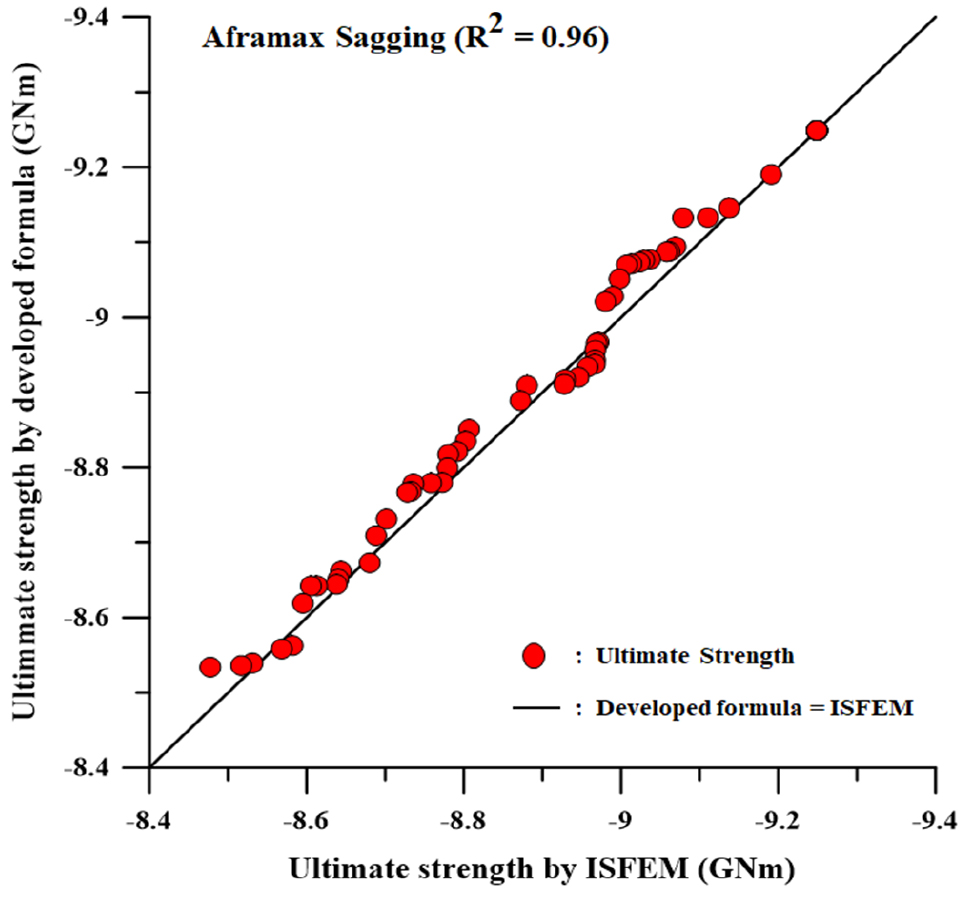
Table 6을 적용한 식 (3a), (3b)의 일치성을 동일한 방식으로, 임의 시나리오에는 X1= 5%, 25%, 55%, 85%를 가정하였으며 일치성을 검증한 결과를 다음 Figs. 24, 25와 같이 도식화 하였다.
6. 결론 및 고찰
본 연구의 목적은 대형 이중선체 유조선 (VLCC, Suezmax, Aframax)의 좌초 사고 (grounding) 시 선각 잔류 최종강도를 쉽게 평가 할 수 있는 경험식 개발이다. ‘damaged element removal method’을 적용하였으며, ISFEM기법을 사용하는 ALPS/HULL 해석프로그램을 사용하였다. 좌초의 폭 방향 위치 (X1) 및 암초의 침투 깊이 (X2) 에 따른 정량적 좌초 손상 시나리오를 설정하였으며, 잔류 최종강도 감소와 변수의 영향을 고려하여 경험식을 개발하였다. 개발된 경험식의 정확도는 다음과 같다.
⏹ VLCC 이중선체 유조선
- 호깅: 97%
- 새깅: 98%
⏹ Suezmax 이중선체 유조선
- 호깅: 96%
- 새깅: 95%
⏹ Aframax 이중선체 유조선
- 호깅: 96%
- 새깅: 96%
본 연구에서 개발된 경험식은 운항 중 선박 좌초(grounding) 사고 시 선각의 잔류 최종강도를 빠르게 계산하고, 이에 따른 후속 조치 및 2차사고 예방에 도움이 될 것으로 사료된다.
Acknowledgments
이 논문은 2017년도 정부(교육부)의 재원으로 한국연구재단의 지원을 받아 수행된 기초연구사업임 (No. NRF-2017R1A6 A3A11036179).
References
- ALPS/HULL, 2012. A computer program for progressive collapse analysis of ship hulls, Advanced Technology Center, DRS System Inc., MD, USA.
-
Baek, S.J., Sohn, J.M., Paik, J.K. & Kim, S.J. 2018. Development of a method for prediction of residual strength for prevention of secondary accidents on large oil tankers subjected to collisions. Journal of the Society of Naval Architects of Korea, 55(2), pp.144-152.
[https://doi.org/10.3744/SNAK.2018.55.2.144]

-
Cho, S.R. Park, J.Y. Song, S.U. & Park S.H., 2018. Scale effects on the structural behavior of steel unstiffened plates subjected to lateral collisions. Journal of the Society of Naval Architects of Korea, 55(2), pp.178-186.
[https://doi.org/10.3744/SNAK.2018.55.2.178]

- IACS, 2009. Guideline for rule development - ship structure, International Association of Classification Societies, London, UK.
- IACS, 2014. Common structural rules for bulk carriers and oil tankers, International Association of Classification Societies, London, UK.
- IACS, 2017. Common structural rules for bulk carriers and oil tankers, International Association of Classification Societies, London, UK.
- IMO, 2000. Recommended longitudinal strength, SOLAS/2, Maritime Safety Committee, International Maritime Organization, London, UK.
- IMO, 2003. Revised interim guidelines for the approval of alternative methods of design and construction of oil tankers under regulation 13F(5) of Annex I of MARPOL 73/78, Maritime Safety Committee, International Maritime Organization, London, UK.
- ISO, 2007. International standard ISO 18072-1, Ships and marine technology-ship structures, Part1: general requirements for their limit state assessment, Geneva, Switzerland.
- ISSC, 2012. Committee III.1 ultimate strength, 18th International Ship and Offshore Structures Congress, Rostock, Germany, 9-13 September.
- ITOPF, 2017. Oil tanker spill statistics 2017, The International Tanker Owners Pollution Federation, Available at: http://www.itopf.com/knowledge-resources/data-statistics/statistics/ [Accessed 17 September 2018].
-
Lee, S.G., Lee, J.S., Lee, H.S., Park, J.H. & Jung, T.Y., 2016. Full-scale ship collision, grounding and sinking simulation using highly advanced M&S system of FSI analysis technique. Proceedings of 11th International Symposium on Plasticity and Impact Mechanics, New Delhi, India, 11-14 December 2016, pp.1507-1514.
[https://doi.org/10.1016/j.proeng.2016.12.232]

-
Paik, J.K., Kim, D.K., Park, D.H., Kim, H.B., Mansour, A.E. & Caldwell, J.B., 2013. Modified Paik-Mansour formula for ultimate strength calculations of ship hulls. Journal of the Ships and Offshore Structures, 8(3-4), pp.245-260.
[https://doi.org/10.1080/17445302.2012.676247]

- Paik, J.K., Kim, D.K., Park, D.H. & Kim, M.S., 2012. A new method for assessing the safety of ships damaged by grounding. Journal of the International Journal of Maritime Engineering, 154(A1), pp.1-20.
- Paik, J.K. & Thayamballi, A.K., 2003. Ultimate limit state design of steep-plated structures, John Wiley & Sons, Chichester, UK.
-
Prabowo, A.R., Baek, S.J., Cho, H.J., Byeon, J.H., Bae, D.M. & Sohn, J.M., 2017. The effectiveness of thin-walled hull structures against collision impact. Latin American Journal of Solids and Structures, 14, pp.1345-1360.
[https://doi.org/10.1590/1679-78253895]

